Thread is one of the common geometric features in mechanical engineering and is widely used. There are many processing techniques for threads, such as rolling and twisting based on plastic deformation, turning, milling, tapping and threading, thread grinding, thread grinding, etc. based on cutting. Among them, thread turning is one of the commonly used processing methods for single or small batch production. As a CNC lathe, thread turning is one of its basic functions.
1, thread turning processing features
Thread CNC machining is different from contour machining. Its characteristics are as follows: thread machining is a forming process, and the cutting edge is long. It is prone to boring and knives. Generally, it requires multiple cutters to complete; to ensure the lead (or Pitch) Accurate, must have proper cutting and cutting length; The thread shape and the tooth angle are basically guaranteed by the shape of the tool. Therefore, the shape and correct installation of the tool directly affect the quality of the thread form; The feed rate and spindle speed must maintain a strict gear ratio, ie F = Ph (mm / r), therefore, constant line speed control is prohibited during machining; the cutting speed of thread cutting is generally not high, so that no built-up edge occurs. Or the plastic damage of the tool is the principle.
2, thread turning processing
There are right-handed and left-handed threads in the thread. The machining method is related to the spindle steering, tool position and feed direction. The external thread is taken as an example, and the processing method is as shown in Fig. 1. The way the internal thread is machined is analyzed by the reader.
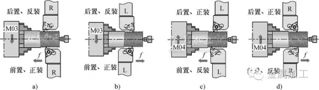
Figure 1 External thread processing method
a), d) right-hand thread b), c) left-hand threadFigure 1a shows the common right-hand thread machining method, spindle forward rotation, front or rear reverse loading tool, and feed from right to left. If the feed direction is reversed, the left-hand thread is machined, as shown in Figure 1b.
Figure 1c shows left-hand thread machining, spindle reversal, pre-reverse or rear-mounted tooling, and feed from right to left.
If the feed direction is reversed, it is a right-hand thread, as shown in Figure 1d.
3 thread turning method
(1) Infeed mode The thread machining must be multi-blade cutting. The feeding method is as follows, as shown in Figure 2.

Figure 2 Feeding method
a) Radial feed b) Lateral feed c) Improved lateral feed d) Left and right alternate feed1) The radial feed (Fig. 2a) is the basic feed mode. The programming is simple. The left and right cutting edges have uniform wear on the flank, and the fit between the tooth and the cutter head is high. However, the chip control is difficult and vibration may occur. The tool tip has a large load and a high temperature. Suitable for small pitch (lead) thread machining and thread finishing.
2) Lateral feed (Fig. 2b) is a more basic feed mode. It has a special compound fixed cycle command programming, which can reduce the cutting force and facilitate the chip discharge control. However, due to the pure one-side cutting, the left and right cutting edges The wear is uneven and the right flank wear is large. Suitable for roughing of slightly larger pitch (lead) threads.
3) Improved lateral feed (Fig. 2c) Due to the slight change of the feed direction, the right cutting edge also participates in a certain degree of cutting, which suppresses the wear of the right flank face to some extent and reduces the cutting heat. , improved the lack of lateral feeding.
4) The left and right alternate feeds (Fig. 2d) are characterized by uniform wear on the left and right cutting edges, which can extend tool life and facilitate cutting and discharge control. The disadvantage is that the programming is slightly complicated. Suitable for machining large teeth and large pitch threads, even for trapezoidal threading, recommended for use with programming capabilities.
In addition, a layered cutting feed method is often used when machining trapezoidal threads.
(2) Infeed depth (also known as cutting depth) There are two ways to select the depth of the infeed for multiple cuttings—the constant cutting area and the constant cutting depth, as shown in Figure 3.
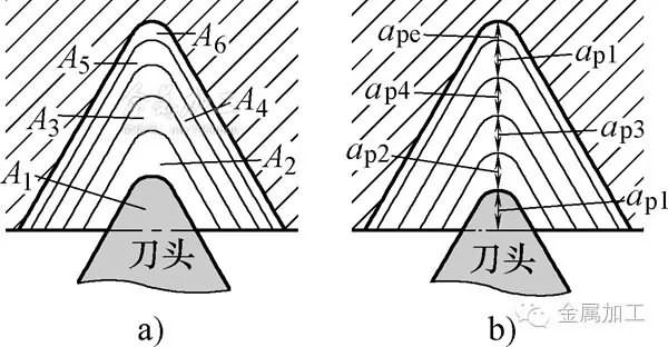
Figure 3 Infeed depth control a) Constant cutting area b) Constant cutting depth
1) Constant cutting area feed, the cutting area of ​​each infeed is equal, ie Ai=constant. This method is the most commonly used method for CNC threading, and usually has the highest machining efficiency; the cutting force is uniform for each pass, which is beneficial to improve tool life.
2) Constant cutting depth feed, each cutting depth is equal, ie api = constant. In this way, the chip thickness is constant and the chip shape can be optimized. The downside is that there are more passes, just as a supplement.
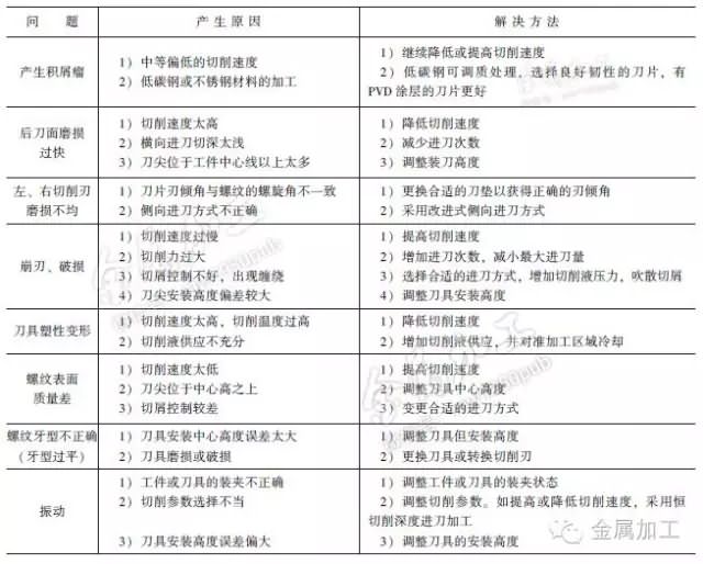
4 thread processing common problems and solutions
See Table 1 for common problems and solutions for thread processing.
Table 1 Common problems and solutions for thread processing
die cavity
- A hollow or recessed section of a die into which the punch forces the metal to form it.
- Mold cavity is a mold term for production and manufacturing, that is, the part that constitutes the product space is called a molded part (that is, the entire mold), and the part that molds the outer surface of the product (mold) is called a cavity
-
The concave part is the cavity, also known as the front mold or master mold,
The corresponding raised part is called the core. Also known as back mold or male mold.
The cavity of the mold is closed with the core, and the gap in the middle is the product.
Cavities Components,Cavity And Core,Plastic Mold Cavity,Plastic Mold Cavity Inserts
Dayue Precision Technology (Dongguan) Co., Ltd. , https://www.dayuechn.com