Example of the Insertion Force Tester Test
The 1220SA plug-in force tester is not only capable of measuring the insertion force of connectors, but also offers a variety of additional functions such as break force testing, constant tensile stress testing, impedance testing, single pin retention testing, and positive force testing. Below are detailed operation instructions to help you use the device effectively.
**1. Insertion Force Test**
1. Choose the measurement mode: set it to two-way measurement with a speed range of 1~300 (standard machine speed). You can adjust the number of tests from 1 to 10,000,000. Before starting, ensure that the "start measuring position" is correctly set and the origin is checked.
2. Insert the male and female connectors of the tested product into the clamps. Ensure that the clamps are vertical and that the automatic centering device is positioned near the center. Avoid any tilting, as this could interfere with the auto-centering function or damage the device.
3. Apply the load, reset to zero, and press the move button on the panel to separate the male and female ends of the test product. Do not completely remove the connector; monitor the display for movement.
4. Set the test stroke. It should be slightly less than the actual stroke—approximately 0.1–0.2 mm.
5. After setting all parameters, click “File,†then “Pre-set Storage†to save the file. The filename must only contain letters, numbers, periods, and hyphens—no spaces allowed.
6. Begin the test on the screen.
If the stroke cannot be found automatically, use a height gauge to measure the insertion stroke of the male plug. Adjust the position of the connectors accordingly and set the stroke. Also, ensure the stroke does not exceed the measured stroke. The starting position is equally important.
**2. Break Test**
1. Clamp the test product into the upper or lower clamp and adjust the height so that it is properly secured.
2. Set the mode to “Break Test.†The stroke should match the actual stroke of the product so that it can be fully pulled out.
3. Set the speed, number of cycles, and save the file.
4. Return to zero and re-clamp the test product. Note: do not return to zero after clamping.
5. Perform the test.
**3. Pin Test**
1. Connect the sensor interface to the test rod and lower the fixture. Adjust the position appropriately.
2. Set the load measurement range to be higher than the maximum withdrawal force of the product. The stroke measurement range should be less than the stroke above the insulation surface of the PIN. This prevents the stroke from being too large, which might cause the actual force value to be missed during the test.
3. Select “Load Zero Position (only when the force starts to count), each time the origin is detected,†and save the settings.
4. Proceed with the test.
Another method is to use the “Single-direction Measurement†mode. The rest of the settings remain the same. In this case, the curve will show a black return force line.
**4. Constant Pressure and Tensile Test**
1. Select “Constant Pressure†in the software. The system will automatically open the “Force†and “Time†data windows. Enter the required force and time values separately, then save the file.
2. Clamp the test product and adjust its position.
3. Start the test. When the set force is reached, the timer will start and run until the set time is completed.
For a constant pull test, the process is similar, except there is no return stroke.
Note: these tests are slower, typically around 30 seconds per cycle.
**5. Longitudinal Force Test**
1. Select the load zero position, ensuring that the origin is detected each time. Set the unit to “gram.â€
2. Connect the test rod to the corresponding test head.
3. Adjust the position and perform the test to measure the corresponding stress at a given stroke.
Some customers require the stress value at the bottom point of the stroke. In such cases, contact the after-sales technician for assistance with the millimeter instrument.
**6. Load-Displacement Test**
If you want to determine the deformation stroke when a certain force is applied, or the force value at a specific displacement, follow these steps:
1. Set the load measurement range to the desired force value and ensure the stroke is sufficiently large.
2. Select the load zero position, with origin detection enabled.
3. Set the speed (typically around 30), number of tests, and save the file.
4. Run the test and check the imax on the waveform diagram to identify the required stroke.
**7. Contact Resistance Test**
1. Set up the parameters as you would for a normal insertion force test.
2. In the measurement item column, select the insertion point resistance value.
3. Clamp the male and female connectors using the impedance test fixture.
4. Proceed with the test.
Other extended test options include anti-bending tests, peel force tests, displacement load tests for shrapnel switches, constant tensile life tests, and force value measurements at break. These can all be performed using the 1220SA model. For more detailed instructions, please inquire directly.
Note: The above procedures apply specifically to the 1220SA insertion force testing machine with a patent certificate.
Http://news.chinawj.com.cn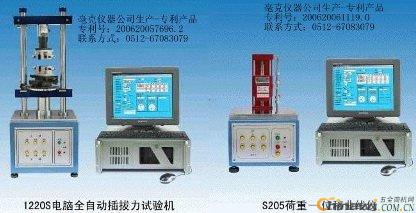 Editor: (Hardware Business Network Information Center) http://news.chinawj.com.cn
The 1220SA plug-in force tester is not only capable of measuring the insertion force of connectors, but also offers a variety of additional functions such as break force testing, constant tensile stress testing, impedance testing, single pin retention testing, and positive force testing. Below are detailed operation instructions to help you use the device effectively.
**1. Insertion Force Test**
1. Choose the measurement mode: set it to two-way measurement with a speed range of 1~300 (standard machine speed). You can adjust the number of tests from 1 to 10,000,000. Before starting, ensure that the "start measuring position" is correctly set and the origin is checked.
2. Insert the male and female connectors of the tested product into the clamps. Ensure that the clamps are vertical and that the automatic centering device is positioned near the center. Avoid any tilting, as this could interfere with the auto-centering function or damage the device.
3. Apply the load, reset to zero, and press the move button on the panel to separate the male and female ends of the test product. Do not completely remove the connector; monitor the display for movement.
4. Set the test stroke. It should be slightly less than the actual stroke—approximately 0.1–0.2 mm.
5. After setting all parameters, click “File,†then “Pre-set Storage†to save the file. The filename must only contain letters, numbers, periods, and hyphens—no spaces allowed.
6. Begin the test on the screen.
If the stroke cannot be found automatically, use a height gauge to measure the insertion stroke of the male plug. Adjust the position of the connectors accordingly and set the stroke. Also, ensure the stroke does not exceed the measured stroke. The starting position is equally important.
**2. Break Test**
1. Clamp the test product into the upper or lower clamp and adjust the height so that it is properly secured.
2. Set the mode to “Break Test.†The stroke should match the actual stroke of the product so that it can be fully pulled out.
3. Set the speed, number of cycles, and save the file.
4. Return to zero and re-clamp the test product. Note: do not return to zero after clamping.
5. Perform the test.
**3. Pin Test**
1. Connect the sensor interface to the test rod and lower the fixture. Adjust the position appropriately.
2. Set the load measurement range to be higher than the maximum withdrawal force of the product. The stroke measurement range should be less than the stroke above the insulation surface of the PIN. This prevents the stroke from being too large, which might cause the actual force value to be missed during the test.
3. Select “Load Zero Position (only when the force starts to count), each time the origin is detected,†and save the settings.
4. Proceed with the test.
Another method is to use the “Single-direction Measurement†mode. The rest of the settings remain the same. In this case, the curve will show a black return force line.
**4. Constant Pressure and Tensile Test**
1. Select “Constant Pressure†in the software. The system will automatically open the “Force†and “Time†data windows. Enter the required force and time values separately, then save the file.
2. Clamp the test product and adjust its position.
3. Start the test. When the set force is reached, the timer will start and run until the set time is completed.
For a constant pull test, the process is similar, except there is no return stroke.
Note: these tests are slower, typically around 30 seconds per cycle.
**5. Longitudinal Force Test**
1. Select the load zero position, ensuring that the origin is detected each time. Set the unit to “gram.â€
2. Connect the test rod to the corresponding test head.
3. Adjust the position and perform the test to measure the corresponding stress at a given stroke.
Some customers require the stress value at the bottom point of the stroke. In such cases, contact the after-sales technician for assistance with the millimeter instrument.
**6. Load-Displacement Test**
If you want to determine the deformation stroke when a certain force is applied, or the force value at a specific displacement, follow these steps:
1. Set the load measurement range to the desired force value and ensure the stroke is sufficiently large.
2. Select the load zero position, with origin detection enabled.
3. Set the speed (typically around 30), number of tests, and save the file.
4. Run the test and check the imax on the waveform diagram to identify the required stroke.
**7. Contact Resistance Test**
1. Set up the parameters as you would for a normal insertion force test.
2. In the measurement item column, select the insertion point resistance value.
3. Clamp the male and female connectors using the impedance test fixture.
4. Proceed with the test.
Other extended test options include anti-bending tests, peel force tests, displacement load tests for shrapnel switches, constant tensile life tests, and force value measurements at break. These can all be performed using the 1220SA model. For more detailed instructions, please inquire directly.
Note: The above procedures apply specifically to the 1220SA insertion force testing machine with a patent certificate.
Http://news.chinawj.com.cn
Editor: (Hardware Business Network Information Center) http://news.chinawj.com.cn Danfoss Type Refrigeration Solenoid Valve
NINGBO DOTEC is a refrigeration Solenoid Valve manufacturer and supplier in China for many year.
Options:
1. Port Size: 1/4'' to 2-1/8''
2. Connection: ODF (Solder), SAE (Flare), Flange
3. Coil Type: BE (Clip on, with terminal box), BF (Clip on, with flying leads), BG (Clip on, with terminal box)
4. Coil Voltage: 12VDC, 24VDC, 24VAC, 110VAC, 220VAC, or others
5. Applicable Refrigerants: HCFC, CFC, HFC, etc
Refrigeration Solenoid Valve, Refrigerator Solenoid Valve, Refrigerant Solenoid Valve
NINGBO DOTEC AUTOMATION CO., LTD , https://www.ningbodotec.com