In traditional worm gear machining, the basic worm of a standard worm gear hob (commonly referred to as a hob) matches the working worm that meshes with the worm wheel. Key parameters include module, pressure angle, pitch circle diameter, number of starts, and helix direction and angle, which are consistent with those of the worm. The center distance used during machining is equal to the working center distance, ensuring proper meshing between the worm and the worm wheel. This paper presents an innovative method for machining worm gears using a non-standard large-diameter worm gear hob—essentially a hob with a larger diameter than conventional ones.
**1. Design of Large Diameter Hob**
(1) **Determining Module and Pressure Angle**
For proper meshing between the worm and the worm wheel, the transverse module of the worm wheel must match the axial module of the worm, and the transverse pressure angle of the worm wheel must match the axial pressure angle of the worm. These relationships can be expressed mathematically:
$$ m_{t2} = m_{x1}, \quad \alpha_{t2} = \alpha_{x1} $$
Additionally, the normal module and normal pressure angle of the worm wheel must align with those of the worm:
$$ m_{n2} = m_{n1}, \quad \alpha_{n2} = \alpha_{n1} $$
This ensures that when the hob cuts the worm wheel, its normal module and pressure angle are compatible with the worm wheel, allowing for correct meshing.
(2) **Determining the Outer Diameter of the Large-Diameter Hob**
The outer diameter of the large-diameter hob significantly affects the shape of the worm wheel. As shown in Figure 1, the worm wheel processed by a large-diameter hob has more material removed, resulting in a drum-shaped profile in the tooth direction. While this can improve load capacity and reduce noise under load, excessive drumming may negatively impact the design’s bearing capacity. Therefore, the outer diameter should not exceed five times the module, typically set at $ d_{\text{hob}} \leq d_{\text{hob}} + 5m $.
(3) **Determining the Normal Tooth Thickness on the Index Circle**
The indexing groove width of the hob determines the tooth space of the worm wheel. To maintain consistent mesh clearance, the tooth thickness on the index circle of the large-diameter hob must match that of the standard hob.
(4) **Determining the Helix Angle of the Large-Diameter Hob**
The helix angle of the hob is calculated using the formula:
$$ \lambda_{\text{knife}} = \arctan\left(\frac{n m_{x,\text{knife}}}{d_{\text{knife}}}\right), \quad m_{x,\text{knife}} = \frac{m_{n,\text{knife}}}{\cos \lambda_{\text{knife}}} $$
Where $ n $ is the number of heads, $ d_{\text{knife}} $ is the pitch circle diameter, and $ m_{n,\text{knife}} $ is the normal module.
(5) **Other Parameters of the Large-Diameter Hob**
To ensure proper meshing, the large-diameter hob must have the same spiral direction, number of heads, and type of basic worm as the standard hob.
**2. Machining of Worm Gear**
As the diameter of the large-diameter hob increases, its helix angle decreases. Before installation, the helix angle must be adjusted based on the hob’s outer diameter. During installation, the tool holder must be angled by $ \theta = \beta - \lambda_{\text{knife}} $ to match the worm’s helix angle. Contact spots must be tested and fine-tuned to ensure optimal meshing.
**3. Example Illustration**
A practical example involves a worm gear with a transverse module of 2.5, 30 teeth, and a normal pressure angle of 20°. The corresponding worm has an axial module of 2.5, one head, and a helix angle of 5°6′8″. Based on these parameters, the hob is designed with a pitch circle diameter of 28 mm and a tip circle of 34.25 mm. A large-diameter hob is then created with a slightly smaller axial module (2.4955), a larger pitch circle (38 mm), and a reduced helix angle (3°45′26″). This design improves durability and reduces noise while maintaining efficiency.
**4. Conclusion**
The use of a large-diameter hob allows for improved load capacity, reduced transmission noise, and cost-effective mass production. It provides a viable alternative to standard hobs, especially in applications where performance and longevity are critical.
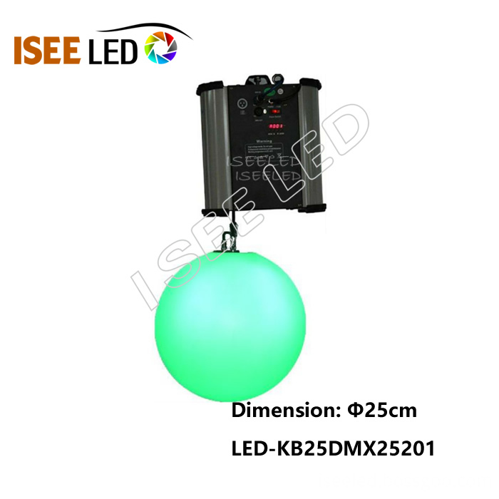
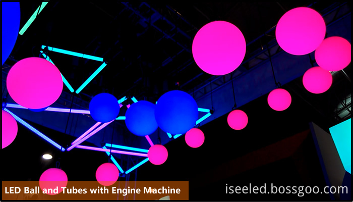
Kinetic led ball is the modern led lights, very popular in the high-end led lighting market, which consist of sports and lightings, the ball can move up and downs by kinetic engine machine which control by dmx 512 together with the led lamps. The kinetic ledball achieve the kinetic sculpture and led light color changing,enrich people's visual sense in sports and colors.
Photo show of Kinetic LED Ball:


Kinetic Led Ball,Dmx Led Lift Ball,Kinetic Sculpture Led Ball,Kinetic Balls
Shenzhen Iseeled Technology Co., Ltd. , https://www.iseeledlight.com