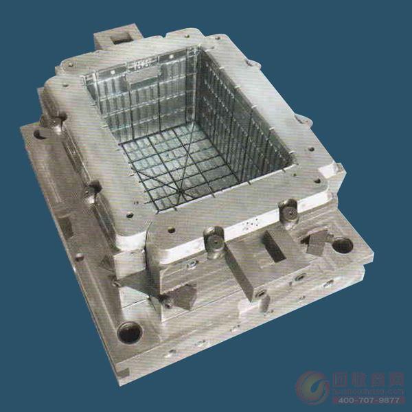
The design points of plastic molds are introduced
1. Generally, the flat product should not be glued in the middle to prevent bending deformation.
2. Under normal circumstances, STP is directly below the RP.
3. When the mold base is large, the interval of STP is 150--200mm.
4. The screw spacing between the upper and lower ejector plates is 150--200mm.
5. When there is a thimble under the slider or the slanting tip is broken, the upper and lower ejector plates are equipped with a forced return mechanism.
6. The draft angle of the finished product is based on the reduction of the glue.
7. When designing the waterway, try not to use the water pipe to directly connect the mold, and use the "O" RING to connect the mold to the mold inlet pipe.
8.SP try to enlarge its diameter and place it below the orthographic area of ​​the finished product.
9. Three principles of cooling waterway: a. rapid cooling, B. uniform mold temperature, C. convenient processing.
10. The slant tip should be rounded from the center of the mold.
11. The KO hole is eccentric with the eccentricity of the sprue bushing, and the maximum inclination angle of the sprue bushing must not exceed 15%%d.
12. For the two-piece mold half, the split stroke between the upper fixed plate and the female template should be controlled by the mechanism. The LP must have a guide bushing on the male die plate. Generally, an LK switch is required.
13. The method of treating the inner barb is generally available with a slant tip, an inner slider, and a stripping plate (ejecting the middle plate), and the ejector tip should be avoided under the slider as much as possible to avoid collision or interference.
14. The general mold core is 20--30mm beyond the contour of the finished product, and should be rounded from the center of the mold. The template is 20--30mm away from the frame of the mold. If there is a slider, the template should be enlarged, especially to avoid interference with the back end. .
15. The spacing between the support column (SP) and the foot pad should be equal to keep the mold balanced.
It is a bit that, when rotated, drills a hole larger than its diameter.
It is including Matrix body and Steel body material .
The Bi-Center Bits provide cost-effective hole opening through installed casing or liner sections.
Engineered cutting structure designed .
High performance cutters from Great factory .
Gauge cutters designed Arc PDC cutters ,which is more abrasive then normal hard alloy gage pads .
Longer working life to save your drilling cost .
Bi-Center Bits,Bi-center PDC drill bits, Matrix body Bi-center bits,Bi Center PDC Bits
CANGZHOU GREAT DRILL BITS CO., LTD , https://www.pdcbits.nl